The Idea
This project was done as part of my Senior Design course at Boise State University. The Mechanical Adaptations Lab at Boise State University, in partnership with Space Tango, is working to send an experimental apparatus to the International Space Station. This experiment involves sending culture samples in a sealed container of fluid. The problem that my senior design group is focused on solving was creating a lid that fits onto the well tray. It was critical that this lid be sealed and solidly attached while also allowing for the samples to be secured. The lid also needed to have plumbing allowing the liquid to be changed every so often without any air bubbles.
The Original Concept
The initial suggestion from the person in charge of the lab was for our group to 3D print the lid from PLA. From my extensive experience of 3D printing I knew that was not really an option. PLA would not be able to hold the liquid long term and there was no way we would be able to reach the tolerances required with an FDM printer. My first thought was possibly printing the parts at my internship out of nylon from an SLS machine.
My Contributions
When tasked with the initial CAD design for our project, my team granted me complete autonomy. I chose to use stainless steel brake lines, typically found in cars, for our plumbing needs. This decision was based on their durability, lightweight nature, ability to be easily shaped, and compatibility with a Schrader valve. I anticipate that this valve will facilitate the removal of air bubbles, akin to bleeding brakes in a vehicle. For securing the lid, I opted for straps that encircle the tray and attach to the lid via screws. To prevent future wear, an embedded nut will replace direct screwing into the plastic. Additionally, I revised the top design, replacing multiple holes with a single one that internally converges to secure the samples.
Fluids Analysis
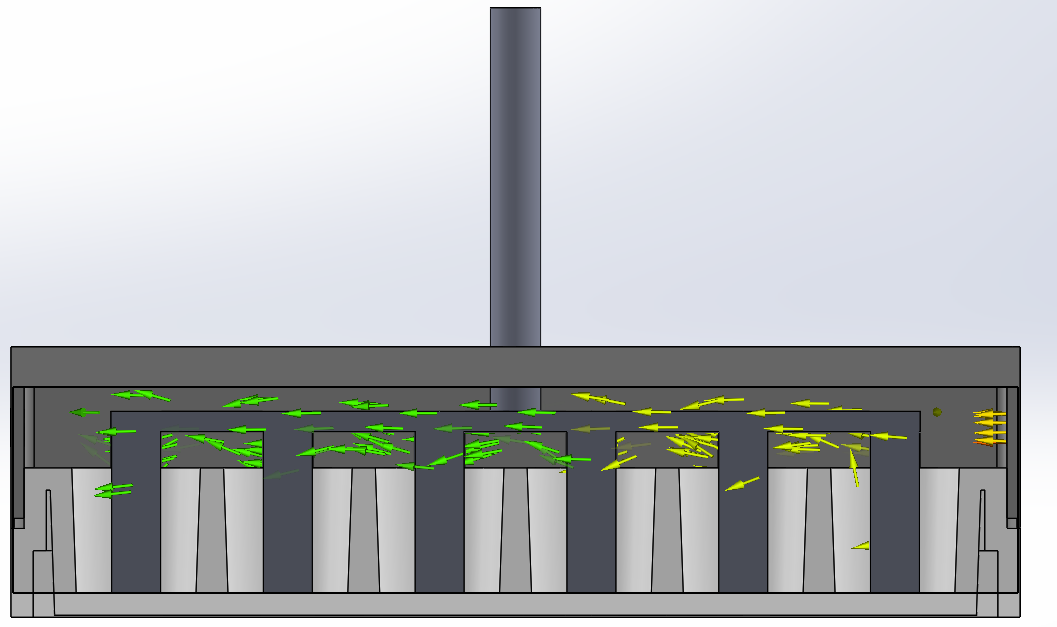
One of the primary requirements for the project was that all of the fluid had to be replaced. This meant there couldn’t be any stagnant areas. I did a quick Solidworks fluid analysis on the design and saw that the fluid flowed over the top and never really entered into the wells. To fix this I added surfaces to the piece holding the samples down that would redirect the flow into each well.
Before
After
Finished Project
In the end I ended up machining both the well tray and the lid out of Delrin on the mill. I then 3D printed a top and bottom clamp that allowed for bolts to be tightened all around it and push the well and lid together with an o-ring in between them. Inside I had a 3D printed part that secured all of the samples and also redirect the flow into each well. The part was pushed on by a screw that went through the top of the lid so that pressure could be applied by tightening the bolt from the outside.
Looking back on the project I should have done a lot more analysis on the sealing. My pass throughs were mostly just threaded into the Delrin, something I wouldn’t do now that I know better. I also would have changed the clamping mechanism in order to get more even pressure across the o-ring.


